
Thermal Management
Cooling-system engineering for aircraft operating where heat is the limiting factor — analysis, sizing, hardware and validated hot-climate performance.
The Problem
Cooling systems that work on a test stand in Europe routinely fail in a Gulf summer. Aircraft and UAV programs discover thermal problems late — after the airframe geometry is frozen, after the engine installation is committed, and after the cheap fixes are gone.
Thermal management is not a radiator selection problem. It is a systems problem that couples ambient conditions, heat-exchanger performance, installation aerodynamics, ducting losses, electrical loads and flight profile. Treating any one of these in isolation is how programs end up with an aircraft that overheats in a hover, in a climb, or on the ground before takeoff.
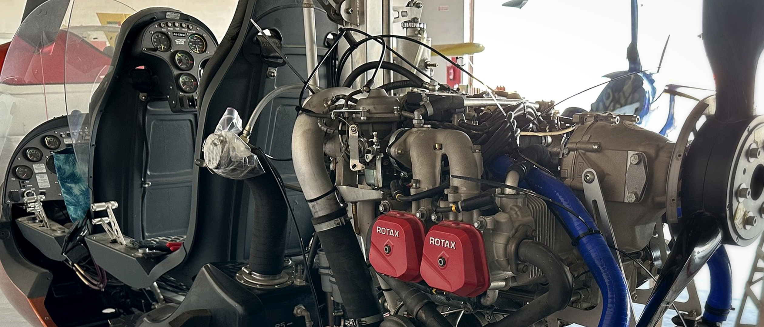
Rotax installation on the REAH flying-laboratory platform, used to develop thermal, propulsion and instrumentation workflows.
Typical Customer Questions
- Will coolant and oil temperatures stay within limits at 50 °C ambient?
- Is the radiator or oil cooler correctly sized — or oversized, paying a permanent drag and weight penalty?
- Does the installation actually deliver the pressure differential and mass flow the heat exchanger needs?
- Is hot-air recirculation or exhaust ingestion silently degrading performance?
- What is the validated hot-day operating envelope of this aircraft?
How We Work
We treat cooling as a system with a heat budget and an air-supply budget, and we close both with evidence:
- Engineer. Define the thermal requirement — heat rejection across the operating envelope, worst-case ambient conditions, and the critical flight phases: usually ground idle, hover or climb, not cruise.
- Simulate. Model the air path as a pressure-differential and mass-flow balance; apply CFD where installation effects dominate — recirculation, propeller-slipstream interaction, inlet spillage.
- Build. Turn the analysis into hardware: ducts, cooler installations, brackets, instrumented components and test rigs.
- Test. Validate with instrumented ground and flight testing under representative conditions, so simulated results become measured results.
- Learn. Compare prediction with measurement, explain discrepancies and update the thermal and airflow models.
- Transfer. Deliver the design rationale, correlated model, test method and acceptance evidence so the customer can sustain the capability.
Every result carries its evidence type: measured, simulated, calculated, assumed or supplier data.
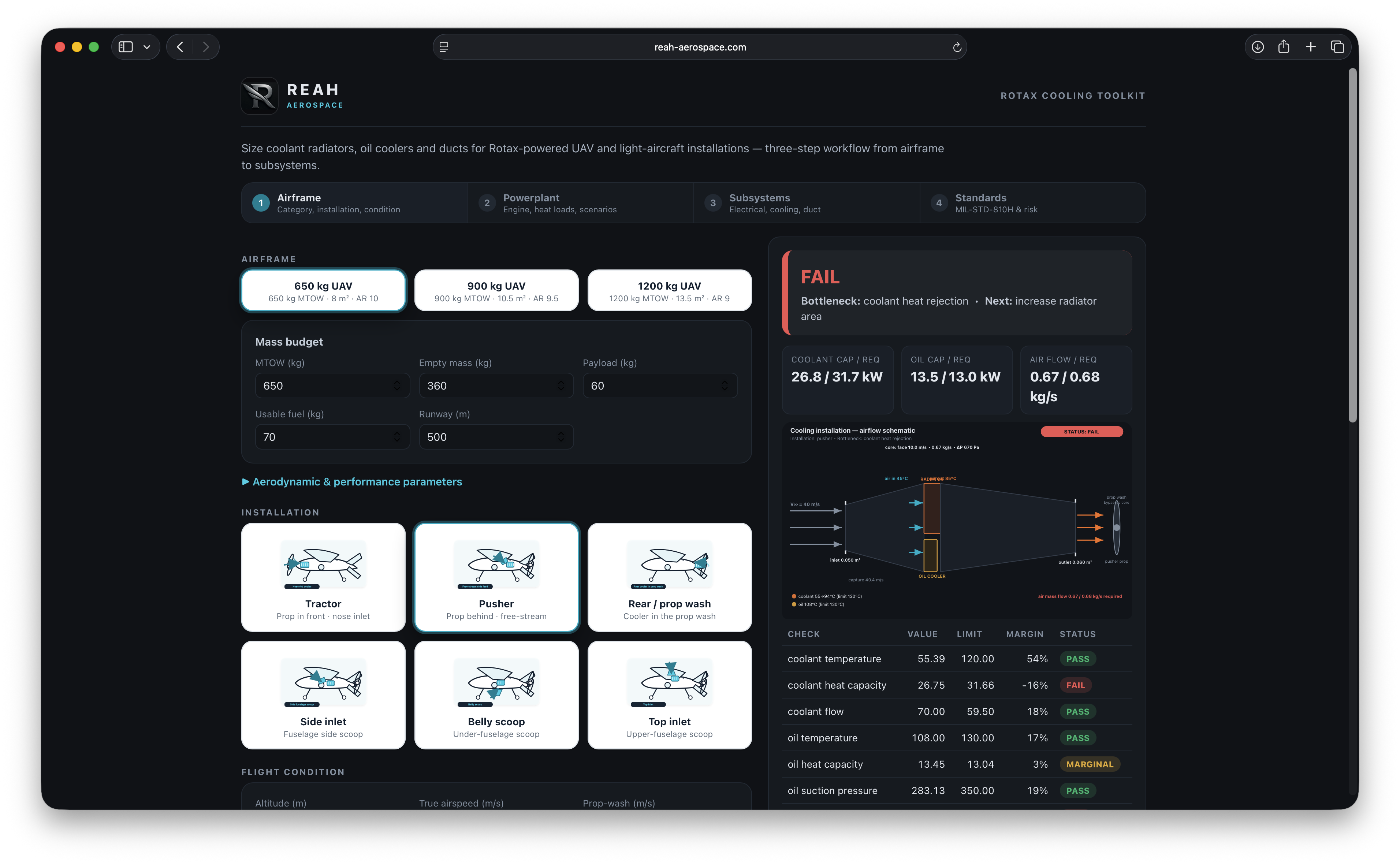
Rotax Cooling Toolkit development interface for sizing coolant radiators, oil coolers and ducts. In development; engineering estimate only until calibrated against supplier and test data.
Tools and Methods
- 1D thermal and flow-network modelling for sizing and trade studies
- 3D CFD (OpenFOAM-based workflows) for installation aerodynamics
- Heat-exchanger performance modelling from supplier data and test correlation
- The Rotax Cooling Toolkit — our internal sizing tool for radiators, oil coolers and ducts
- Instrumentation planning for ground and flight thermal surveys
- Hot-climate operating-envelope analysis
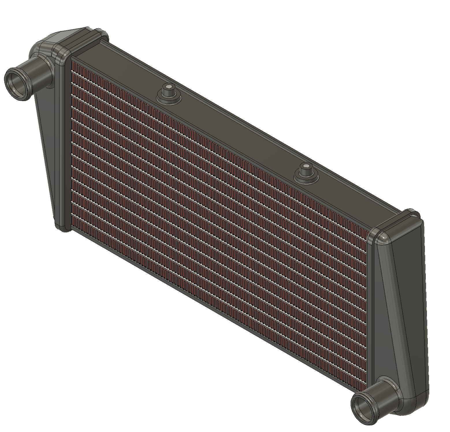
Custom radiator CAD concept for Rotax-class installations, including thermostat and pressure/temperature instrumentation interfaces. Maturity: engineering concept.
Typical Deliverables
- Cooling-system requirements and heat-budget definition
- Radiator and oil-cooler sizing studies with stated assumptions
- Installation CFD analysis with pressure, flow and temperature fields
- Ducting and inlet/outlet design, from concept to prototype hardware
- Test plans, instrumentation specifications and test-data analysis
- A documented hot-day operating envelope
Evidence
REAH demonstrates its methodology through funded engineering work documented in Projects, including the Rotax Gyrocopter Cooling Demonstrator.
Boundaries and Limitations
- Every model defines its validity range; conclusions remain inside the supported conditions.
- Certification programmes receive structured engineering evidence for review by the responsible approval authority.
- Where supplier data is the only available source, results are labelled as such.
Put this discipline against a real aircraft milestone.
Bring the platform, operating condition, present symptom and decision that cannot move forward. REAH will map the complete system and the evidence required.