
Propulsion Integration & Validation
Accountable ownership of propulsion, thermal management, electrical power and installed flight performance—from engineering and instrumentation through representative ground and flight evidence.
The Package
An engine can meet every published requirement and still fail the aircraft mission. Installed performance depends on how propulsion, heat rejection, electrical demand, propeller flow, airframe geometry and the operating profile interact.
REAH owns that combined problem as a defined engineering and validation package. The engagement begins with the flight, qualification or production milestone that must close. It ends with a readiness decision supported by an agreed evidence package, with the models, configuration and test knowledge transferred to the customer team.
The initial focus is unmanned and special-mission aircraft in the UAE and GCC, particularly piston and hybrid-electric platforms in the 50–300 kW class.
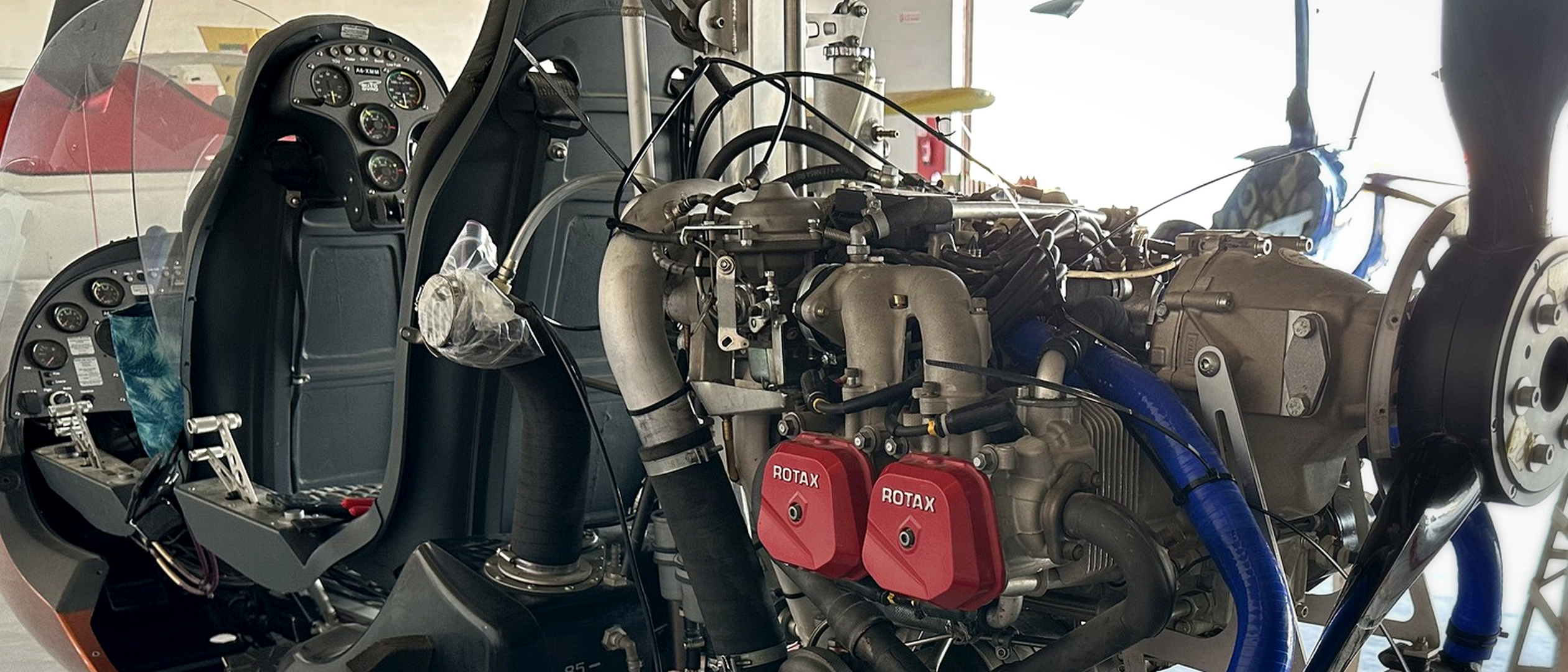
Engine installation on REAH's internal flying-laboratory reference platform, used to develop propulsion, thermal and instrumentation workflows.
When to Engage REAH
- The prototype flies, but thermal or electrical margin disappears in Gulf conditions.
- Installed power, endurance or climb performance does not match the component data.
- A flight or qualification milestone is blocked by an unresolved systems interaction.
- The programme needs instrumentation and representative test evidence, not another desk study.
- A design change must be assessed across propulsion, cooling, electrical demand and flight performance.
- The permanent aircraft-systems or flight-test team is still being built.
Accountable System Boundary
The package connects four technical responsibilities that are often split between suppliers:
- Propulsion. Installed power, induction, exhaust, propeller interaction and manufacturer operating limits.
- Thermal management. Heat rejection, coolant and oil circuits, exchanger sizing, ducting, pressure loss and hot-air recirculation.
- Electrical power. Generation, storage, distribution, mission load and the thermal cost of electrical demand.
- Installed flight performance. The effect of the complete installation on climb, endurance, ground operation and the required mission profile.
Specialist analyses remain connected to one technical owner, one configuration and one acceptance argument.
Five Evidence Gates
- Define. Establish the mission profile, operating envelope, failure symptom, system boundary, programme constraint and acceptance criteria.
- Instrument. Define sensors, locations, sampling, calibration, acquisition, data-quality checks and ground or flight test procedures.
- Engineer. Build the installation model, assess thermal and electrical margins, run CFD where it changes a decision, and develop controlled hardware or configuration changes.
- Validate. Collect representative hot-weather ground and flight evidence, compare it with the agreed criteria and correlate the engineering models.
- Transfer. Deliver the configuration record, assumptions, models, data, test method, decision basis and remaining limitations to the customer team.
REAH can lead the complete package or enter at the blocked gate. In either case, the final evidence remains connected to the original aircraft requirement.
Typical Deliverables
- Propulsion-installation review against manufacturer requirements
- Mission-phase thermal and electrical load model
- Engine-bay airflow, inlet, outlet and recirculation analysis
- Propeller-slipstream and cooling-flow interaction study
- Instrumentation architecture, sensor schedule and data-acquisition plan
- Ground and flight test cards with acceptance criteria
- Installation hardware, ducting, baffle or cooling-interface design support
- Correlated test report and readiness decision
- Configuration, model and evidence handover package
Deliverables are selected to close the defined milestone. They are not a mandatory list of consulting activities.
Gulf Operating Conditions
Representative validation must account for the conditions that change the installed system: high ambient temperature, solar exposure, dust and contamination, extended ground operation, low-speed flight, long endurance and sustained engine or electrical load.
The relevant combination depends on the aircraft mission. REAH defines that combination before selecting test points or claiming margin.
Evidence
REAH is developing and demonstrating the method on its own flying laboratory. The internal programme separates instrumentation architecture, ground baseline, flight baseline, model correlation and modification testing into explicit evidence gates.
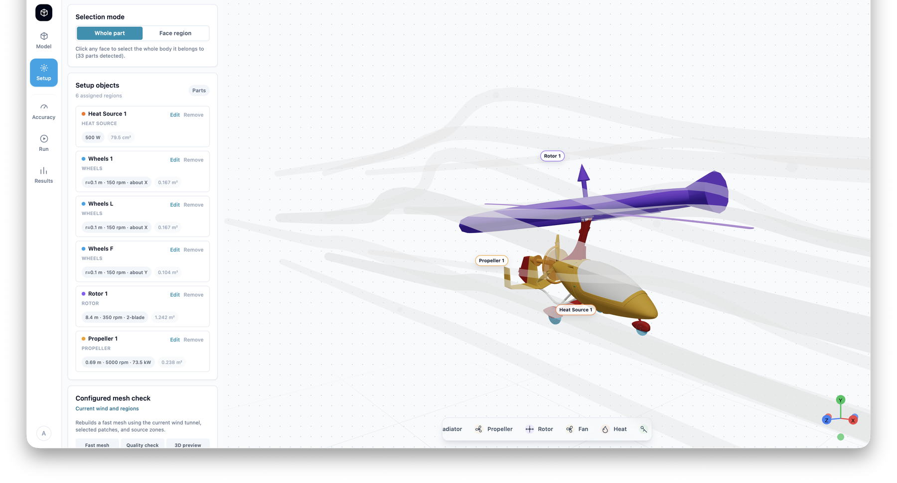
Propeller, rotor, wheel and heat-source regions assigned together in REAH CFD Studio. The image demonstrates the modelling workflow; it is not flight-validation evidence.
Boundaries and Limitations
- Engine internals and engine certification remain the manufacturer's domain; REAH engineers and validates the installed system around them.
- Manufacturer installation manuals, approved data and operating limits take precedence over REAH analysis.
- Flight testing depends on aircraft readiness, permissions, safety review, operating area and an agreed test plan.
- A simulation becomes a validated model only after correlation against representative measurements within a stated validity range.
- REAH does not claim aircraft certification, regulatory approval or platform qualification unless that scope and evidence are explicitly established.
Put this discipline against a real aircraft milestone.
Bring the platform, operating condition, present symptom and decision that cannot move forward. REAH will map the complete system and the evidence required.