
Aerodynamics & CFD
Computational fluid dynamics and installation aerodynamics for UAVs and light aircraft, with clearly stated model validity.
The Problem
Most aerodynamic surprises on small aircraft and UAVs are not wing problems. They are installation problems: cooling inlets that spill, pusher propellers swallowing disturbed fuselage wake, antenna and payload fairings interacting with control surfaces, exhaust plumes going where they should not.
These effects are hard to estimate by hand, expensive to discover in flight test, and exactly what CFD is good at — provided the boundary conditions and limits are stated up front.
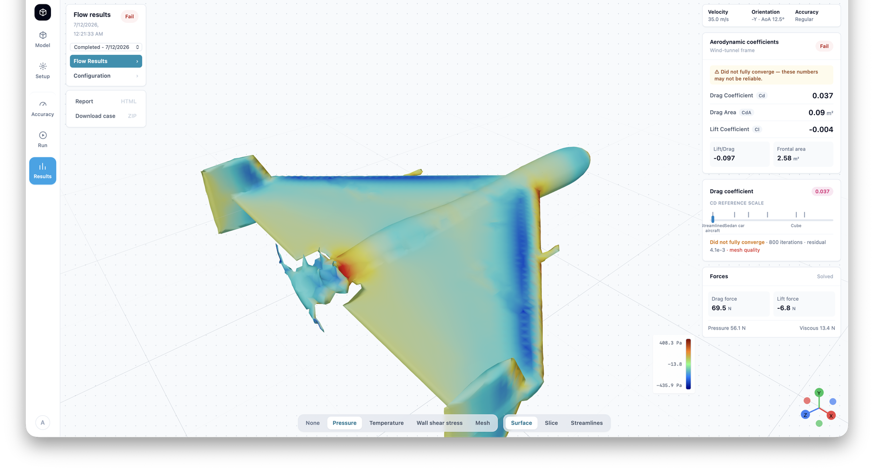
REAH CFD Studio development interface showing surface-pressure results for an external-flow case. The run is flagged as not fully converged, so the coefficients shown are diagnostic output rather than validated aerodynamic data — the tool surfaces that warning rather than hiding it.
Typical Customer Questions
- How much cooling drag is this installation costing, and where does it come from?
- What does the flow field around the propeller, inlet or payload actually look like?
- Will this modification change stability, control or engine cooling behaviour?
- Can we evaluate design variants before committing to tooling?
The REAH Approach
- Start from the engineering question, not the mesh. We define what decision the simulation must support and what accuracy that decision actually requires.
- Choose the cheapest sufficient model. Panel methods and empirical correlations where they are adequate; RANS CFD where installation effects dominate; higher-fidelity approaches only when the question demands them.
- State boundary conditions explicitly. Every published result carries its assumptions — flow conditions, turbulence modelling, geometry simplifications and mesh characteristics.
- Correlate where possible. Simulation results are labelled simulated until they are correlated against measurement; then, and only then, do they become validated.
Tools and Methods
- OpenFOAM-based RANS workflows for external aerodynamics and internal ducting
- Automated, version-controlled case setup — every simulation is reproducible
- Mesh-sensitivity and convergence documentation as standard practice
- Propeller and rotor modelling via actuator-disk and body-force methods
- Post-processing focused on engineering quantities, not just pretty pictures
Typical Deliverables
- Installation aerodynamics studies with quantified pressure and flow fields
- Cooling-airflow and duct-loss analysis
- Drag breakdown and design-variant comparisons
- Reproducible simulation cases delivered with the report
- Simulation-validation test plans
Evidence
Our CFD methodology is demonstrated through internal engineering work, currently the Rotax Gyrocopter Cooling Demonstrator, which applies these workflows to a real cooling installation. Validated customer results will be published only with customer consent.
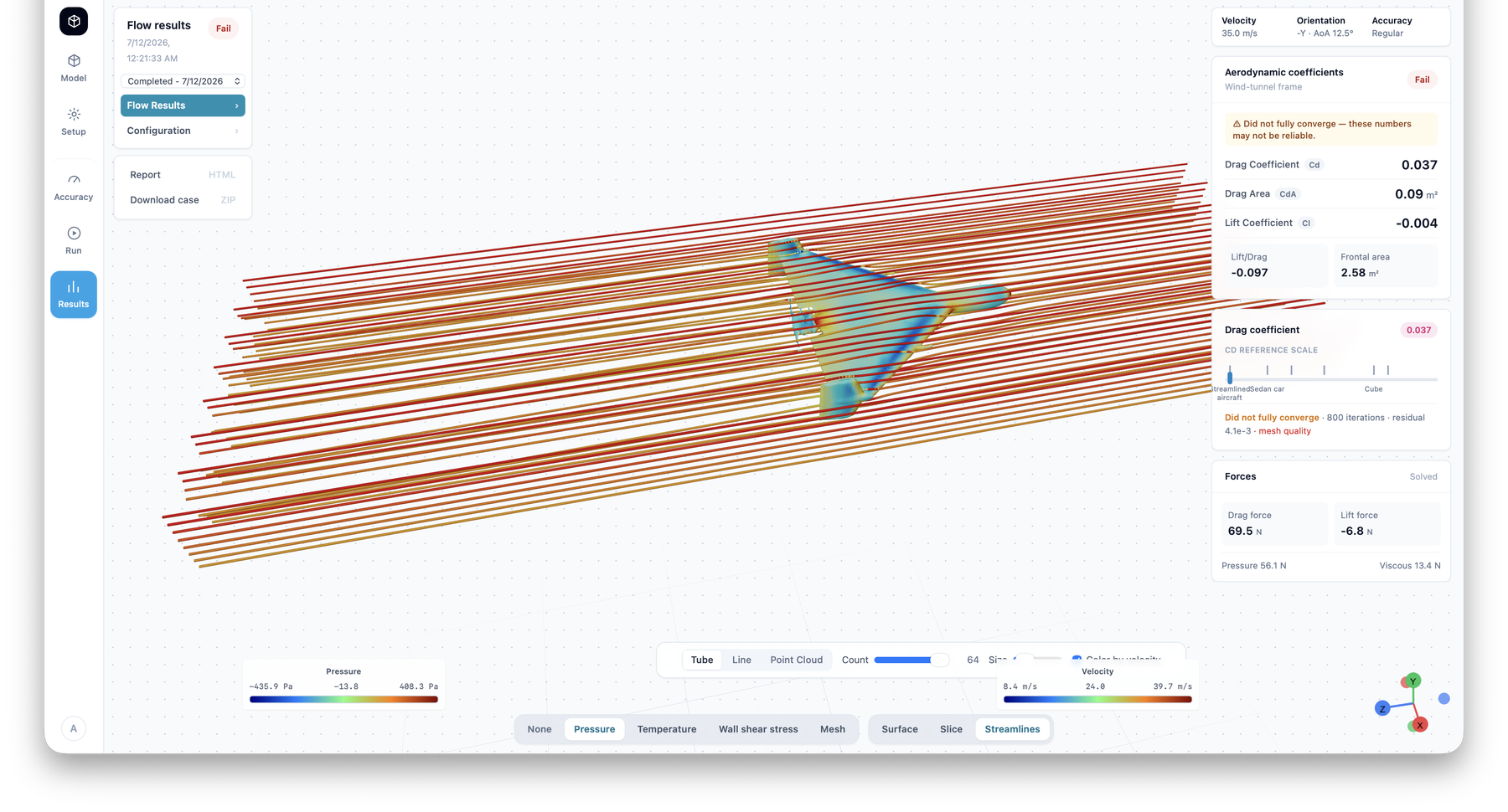
The same case reviewed as velocity-coloured streamlines in REAH CFD Studio, showing the analysis and review toolchain.
Boundaries and Limitations
- CFD supports design decisions; representative testing provides the correlation evidence.
- We publish mesh, convergence and modelling limitations alongside every result.
- Validation status follows the evidence: simulated, correlated or measured.
Put this discipline against a real aircraft milestone.
Bring the platform, operating condition, present symptom and decision that cannot move forward. REAH will map the complete system and the evidence required.