
Rotax Gyrocopter Cooling Demonstrator
An open engineering study of cooling-system performance on a Rotax-powered gyrocopter in hot-climate operation — methodology, simulation and planned validation, published as the work happens.
Platform
Rotax-powered gyrocopter
Programme
REAH engineering programme
Evidence published
Engineering Question
Can the cooling installation of a Rotax-powered gyrocopter maintain coolant and oil temperatures within operating limits across the full flight envelope — including ground operation and climb — in hot-climate ambient conditions?
Why a Demonstrator
This is a REAH-funded engineering project, published to show how we approach a real thermal-management problem: how the requirement is defined, how the installation is modelled and simulated, and how simulation is validated against measurement. Every piece of evidence published here is labelled with its type.
Platform Context
The study platform is a Rotax-powered gyrocopter — a configuration that combines several thermally demanding traits: liquid- and air-cooled engine circuits, a pusher-propeller installation that couples the cooling exit flow with the propeller inflow, low climb airspeeds, and operation in high ambient temperatures.
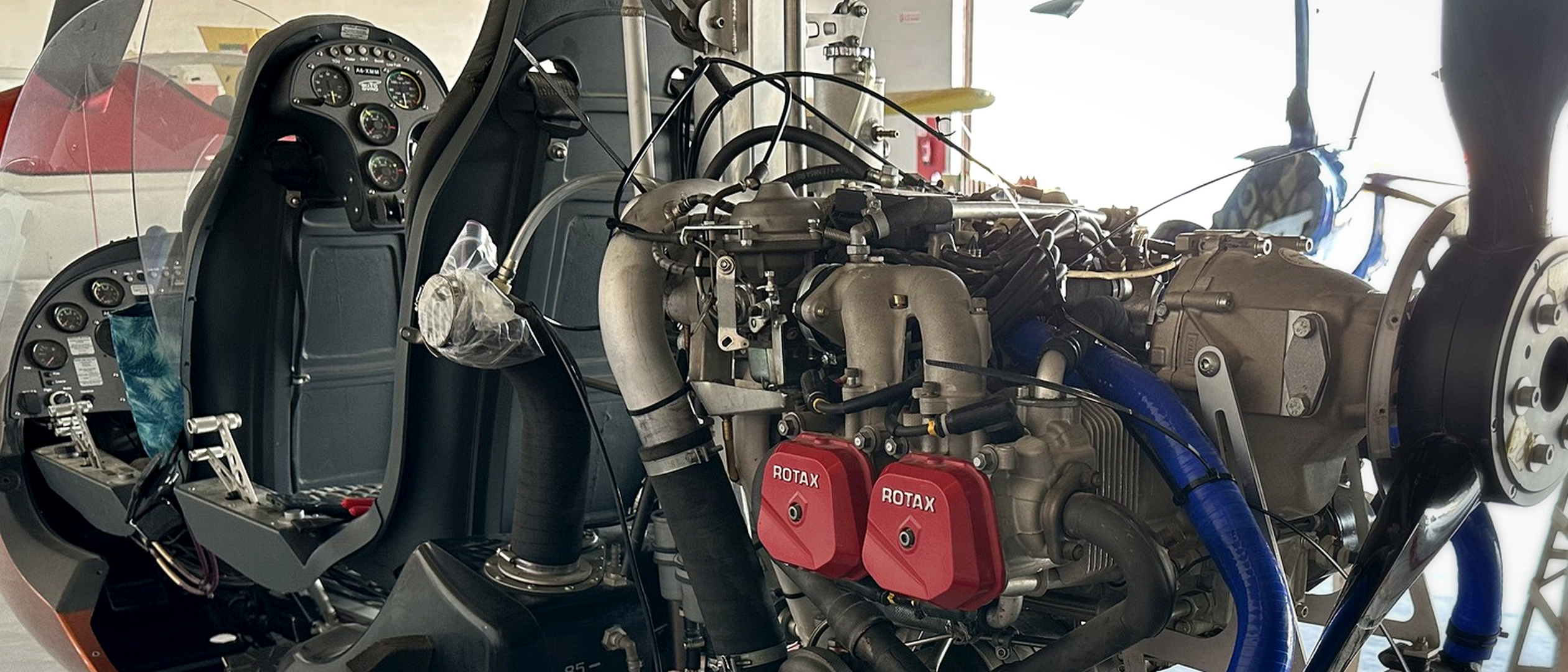
Rotax installation on the REAH flying-laboratory platform, used to develop the thermal, propulsion and instrumentation workflows behind this study.
The first technical release will define the platform configuration, boundary conditions and instrumentation architecture before baseline testing begins.
Methodology
The study follows the standard REAH thermal workflow:
- Heat-budget definition — engine heat rejection across the operating envelope, from supplier data and literature, labelled as such.
- Flow-network model — a 1D pressure-differential and mass-flow balance of the cooling air path: inlet, ducting, heat exchangers, exit.
- Installation CFD — OpenFOAM-based simulation of the installation flow field, including propeller slipstream interaction and recirculation assessment.
- Ground and flight measurement — instrumented testing to correlate the models, turning simulated results into validated ones.
Evidence Programme
- Supplier-data baseline — in progress. Compile engine limits, heat-rejection inputs and installation constraints.
- Heat-budget definition — next release. Establish the governing thermal loads across the operating envelope.
- Flow-network model — next release. Quantify pressure losses and cooling-air mass flow through the installed path.
- Installation CFD — follows model definition. Resolve recirculation, inlet and exit behaviour, and propeller interaction.
- Ground correlation — validation gate. Compare measured temperatures and pressures with prediction.
- Instrumented flight survey — operational gate. Extend correlation across representative flight conditions.
Current Engineering Position
The programme is establishing its supplier-data baseline and model definition. The first reviewed release will publish the heat budget, assumptions and flow-network method that govern the later CFD and test campaign.
Evidence Scope
- Findings from this platform require installation-specific analysis before transfer to another aircraft.
- Simulation remains classified as uncorrelated until the ground and flight validation gates are complete.
Next Validation Step
Publication of the heat-budget definition and flow-network model, followed by the first instrumented ground-test data.
Working on a similar problem?
Apply this engineering and evidence method to your aircraft, component or validation programme.