
Flying Laboratory
REAH's physical test platform for turning thermal, propulsion, power and component-substitution assumptions into measured engineering evidence under representative Gulf operating conditions.
Platform
Pusher-configuration gyrocopter testbed
Programme
REAH engineering programme
Evidence published
Where Aerospace Capability Becomes Evidence
Models earn trust through measurement.
The REAH Flying Laboratory is the physical test platform where engineering assumptions meet heat, vibration, airflow, installation constraints and operational reality. It is being developed to create measured evidence, improve reusable engineering models and establish validation methods that can transfer into customer programmes.
Its purpose is to answer engineering questions that catalogue data and simulation alone cannot resolve: installed thermal behaviour, propulsion interactions, power demand, component substitution and real operating margin.
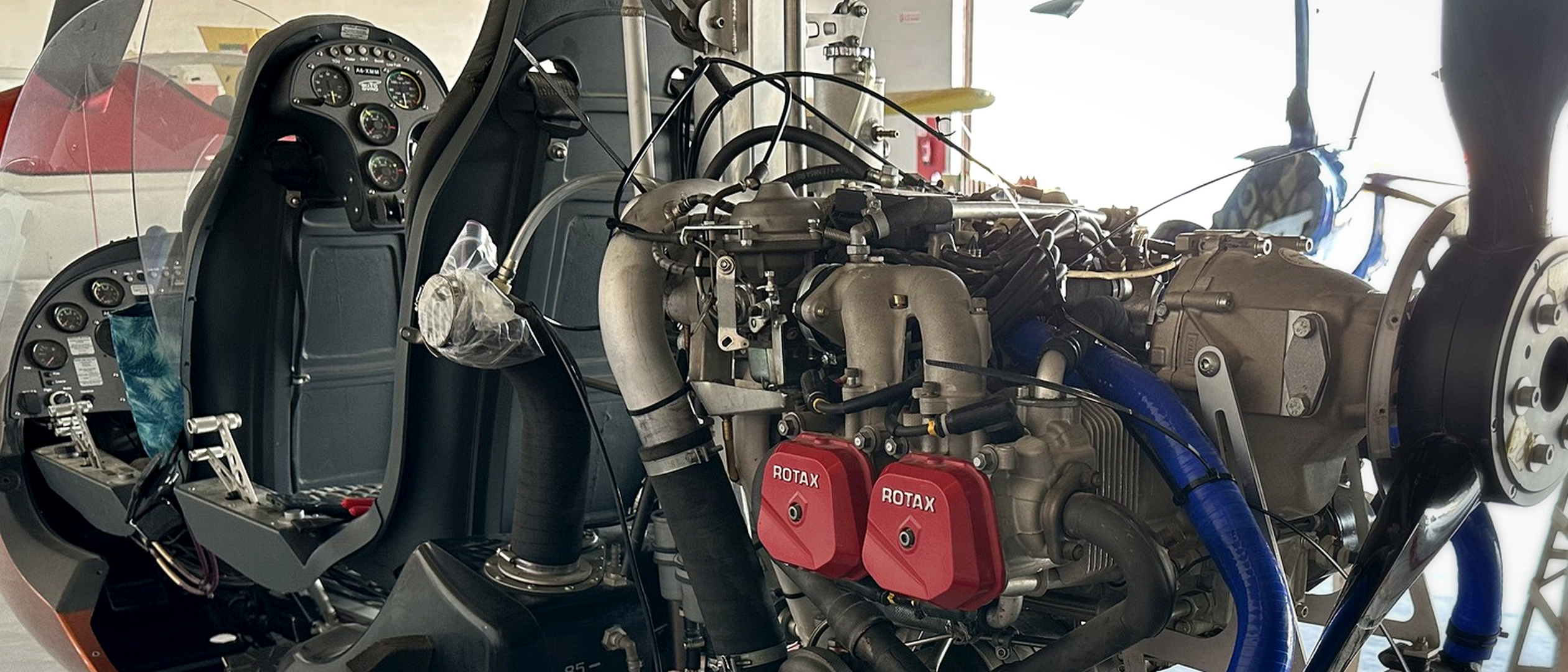
Rotax-powered gyrocopter installation used as REAH flying-laboratory reference hardware. This is the physical platform; instrumentation integration and validation campaigns remain in development.
Evidence Package 01 — Test Definition
Released scope: physical reference platform, engineering question, proposed measurement architecture, baseline test matrix and data structure. Evidence status: the platform is present; instrumentation and testing remain in development. This package contains no measured performance claim.
Configuration Record — Release 01
The evidence package is tied to a controlled reference configuration so that later measurements can be interpreted and repeated.
| Configuration item | Release 01 definition | Evidence status |
|---|---|---|
| Test asset | Pusher-configuration gyrocopter | Physical platform present |
| Propulsion reference | Installed Rotax-class engine and cooling installation shown above | Physical hardware photographed |
| Primary investigation | Installed thermal, propulsion and electrical behaviour in demanding ambient conditions | Engineering question defined |
| Intended test sequence | Instrumentation checkout, controlled ground baseline, flight baseline, model correlation and comparative modification | Planned progression |
| Configuration control | Aircraft state, sensor installation, calibration references and software version recorded for every dataset | Method defined; records begin at integration |
| Published result status | No ground, flight or correlated dataset released | Not yet measured |
Changes to the installed engine, cooling circuit, duct geometry, electrical loads, instrumentation or logging software will create a new configuration revision. Results from different revisions will not be combined without identifying the change.
Proposed Measurement Architecture
Release 01 defines the channel families required to answer the engineering question. Final sensor selection, range and installation approval remain part of the instrumentation gate.
| Measurement family | Proposed channels | Engineering purpose |
|---|---|---|
| Ambient reference | Outside-air temperature and pressure | Define the environmental boundary condition |
| Coolant system | Engine outlet, cooler inlet/outlet and return temperatures; pressure where approved | Quantify heat rejection and installed thermal margin |
| Oil system | Oil temperature and approved pressure reference | Track lubrication-system thermal behaviour |
| Cooling air | Inlet, core-face and outlet temperatures; differential pressure across the heat exchanger | Resolve available cooling flow and installation loss |
| Propulsion state | Engine speed, manifold pressure or load reference, and available engine parameters | Align thermal response with operating condition |
| Electrical system | Bus voltage and current for defined loads | Establish generation demand and thermal-electrical interaction |
| Aircraft state | Time, ground or flight condition, airspeed and altitude where available | Place every sample in its operating context |
All channels will use a common time base. Calibration reference, engineering units, sample rate, valid range and uncertainty target will be stored with the channel definition rather than left in a separate presentation.
Baseline Test Matrix
The baseline is designed to separate installation effects from modification effects. Actual execution remains subject to aircraft approval, operating limitations, weather and test safety review.
| Gate | Condition set | Required release output |
|---|---|---|
| Instrumentation checkout | Engine off and controlled system checks | Channel identity, polarity, range and synchronized logging confirmed |
| Ground baseline | Stabilised idle and approved power points across recorded ambient conditions | Repeatable time histories and configuration record |
| Thermal transition | Approved power change followed through temperature response | Response rate, peak values and stabilisation behaviour |
| Flight baseline | Representative approved flight conditions | Reviewed flight dataset with operating-state markers |
| Correlation | Matching model boundary conditions and measured cases | Predicted-versus-measured comparison with discrepancy and uncertainty |
| Comparative test | One controlled configuration change against the baseline | Like-for-like result with all other relevant conditions recorded |
Data Package Structure
Each released dataset will contain four linked records:
- Configuration — aircraft, propulsion, cooling, electrical and software revision.
- Channel dictionary — sensor identifier, location, unit, range, sample rate, calibration reference and uncertainty target.
- Test event log — operating condition, pilot or test marker, environmental context and anomalies.
- Time-series data — synchronized raw values, quality flags and any derived values with the derivation stated.
Raw measurement, corrected measurement, calculated quantity and simulation output will remain separate fields. A plotted line will never be the only surviving record of a result.
Why This Matters to Customer Programmes
Aircraft programmes routinely depend on assumptions that become visible only after installation:
- published component performance that does not represent installed conditions;
- cooling flow altered by ducts, exits, structure and propeller slipstream;
- electrical and thermal margins reduced by mission equipment;
- locally manufactured or substituted parts that require comparative validation;
- models that remain uncorrelated because representative measurements do not exist;
- suppliers who deliver hardware without transferring the method needed to verify it.
The Flying Laboratory gives REAH a controlled environment for developing the instrumentation, test procedures, correlated models and acceptance logic needed to address those risks.
Why This Platform
The pusher-configuration gyrocopter creates a compact and technically demanding installation. The engine, heat exchangers, cooling exits, structure and propeller flow field interact closely. Low-speed ground operation, climb, high ambient temperature and changing power demand expose precisely the installation effects that simplified component analysis can miss.
The platform is also accessible enough to support repeated instrumentation changes, prototype installation and inspection. That makes it useful for developing methods before transferring them to less accessible UAV and light-aircraft installations.
What the Laboratory Will Enable
- Baseline characterisation — establish how the unmodified installation behaves across defined ground and flight conditions.
- Thermal, propulsion and power measurement — capture temperatures, pressures, flow indicators, engine parameters and electrical loads against a common time base.
- Model correlation — compare measurements with thermal, flow-network and CFD predictions, including discrepancies.
- Prototype validation — test ducts, cooling arrangements, sensors and other integration hardware comparatively.
- Component-substitution evidence — define whether an alternative or locally manufactured part meets controlled performance and acceptance criteria.
- Capability transfer — convert the instrumentation architecture, procedures and analysis into methods that customer teams can retain and repeat.
Evidence Progression
The laboratory advances through explicit evidence gates. Each completed gate creates the foundation for the next.
| Evidence gate | Required output | Current status |
|---|---|---|
| Physical reference platform | Aircraft and installed propulsion/cooling hardware available for engineering definition | Present — physical hardware photographed |
| Engineering definition | Test objectives, operating cases, parameters and acceptance questions | In development |
| Instrumentation architecture | Sensor types, locations, ranges, sample rates, uncertainty targets and channel map | In preparation |
| Data-acquisition integration | Installed sensors, synchronized logging, calibration records and configuration record | Planned |
| Ground baseline | Repeatable ground-run dataset across defined ambient and power conditions | Planned |
| Flight baseline | Reviewed dataset across representative flight conditions within the approved envelope | Planned |
| Model correlation | Measured-to-predicted comparison with discrepancies and model updates | Planned |
| Comparative modification test | Baseline-versus-modified evidence using the same controlled method | Planned |
| Transfer package | Reusable sensor architecture, test procedure, data schema and acceptance method | Planned |
Evidence available today
The physical platform and installed Rotax reference hardware are present. Engineering definition and instrumentation architecture are the active programme gates. Ground baseline, flight baseline, model correlation and comparative modification testing follow in sequence.
Evidence Package Release Gates
Evidence Package 01 establishes the test definition. The next releases will add:
- Integration release — installed channel map, sensor ranges, sample rates, calibration references and configuration photographs;
- Ground baseline release — reviewed ground-run data, ambient conditions, anomalies and repeatability assessment;
- Flight baseline release — reviewed flight data within the approved envelope and associated configuration record;
- Correlation release — measured-to-predicted comparison, uncertainty and model changes;
- Comparative release — baseline-versus-modified evidence using the same controlled method.
Publishing the definition before results makes the method inspectable and prevents the test from being designed around a preferred conclusion.
The REAH Learning Loop
- Define the question — state the operational risk and the evidence required to resolve it.
- Model the system — make assumptions and boundary conditions explicit.
- Configure the test — install calibrated instrumentation against a controlled aircraft definition.
- Measure under representative conditions — ground and flight test within the approved operating envelope.
- Compare evidence with prediction — publish agreement, discrepancy and uncertainty.
- Improve and transfer — update the model, hardware and repeatable customer method.
From REAH Aircraft to Customer Capability
The value of the laboratory is not limited to one gyrocopter. Each campaign should leave behind reusable capability:
- a better-correlated thermal or airflow model;
- a tested sensor and logging architecture;
- a repeatable ground or flight-test procedure;
- evidence requirements for substituted or locally manufactured components;
- configuration and acceptance records that can be applied to customer aircraft;
- engineers who understand how to repeat the method after REAH leaves.
That is how an internal test platform becomes customer capability rather than an isolated experiment.
Evidence Scope
- Current published evidence covers the physical platform and reference installation; measured ground and flight datasets follow the evidence progression above.
- The hangar image below visualises the planned instrumented configuration.
- Results from this platform strengthen methods and models; customer aircraft retain installation-specific analysis requirements.
- Testing will remain within the aircraft's approved operating envelope and applicable regulations.
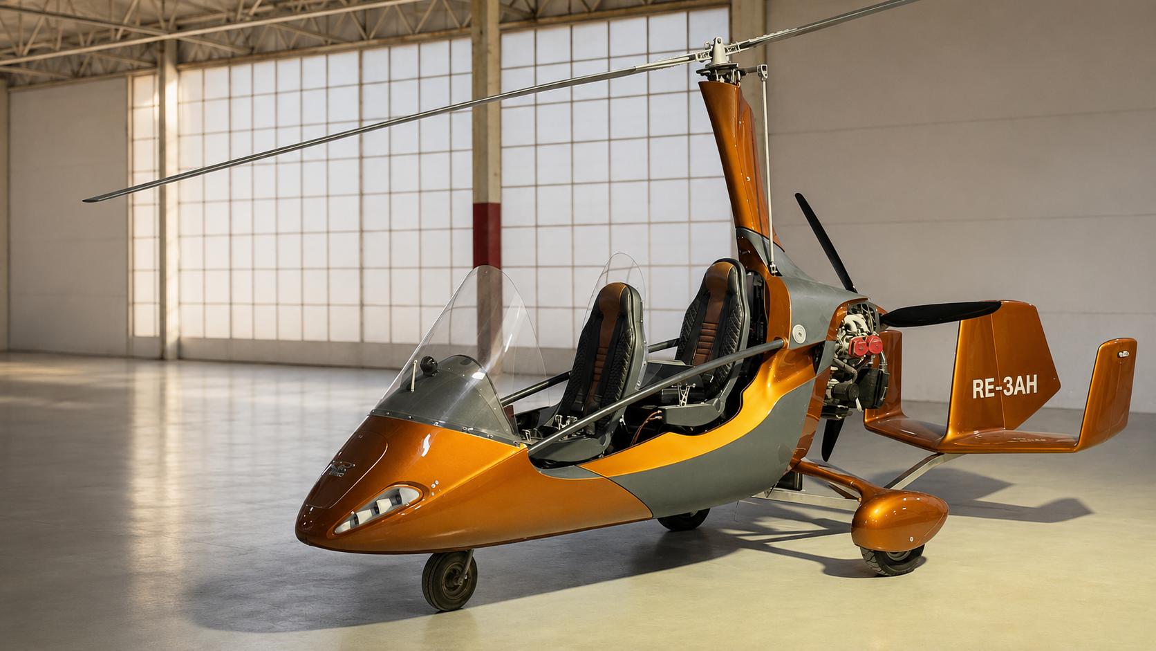
Visualisation of the planned instrumented flying-laboratory configuration.
Working on a similar problem?
Apply this engineering and evidence method to your aircraft, component or validation programme.