
Technical Paper TP-001
Mission-Oriented Evaluation of the Rotax 914 UL and Rotax 912 iS Sport for Low-Altitude Tactical UAV Applications
Continuous propulsion power, hot-day cooling margin and electrical demand in launcher-assisted UAV missions
- Author
- REAH Engineering
- Published
- 2026-07-13
- Reading time
- 8 min
- Access
- Open
Abstract
This technical paper compares the Rotax 914 UL and Rotax 912 iS Sport as propulsion candidates for launcher-assisted low-altitude UAV missions. The analysis focuses on continuous power, 45 °C hot-climate operation, 5 kW continuous electrical generation, pusher-aircraft thermal integration and life-cycle engineering burden. It does not claim that either engine is universally preferable; it shows why mission context, altitude requirement and installed thermal margin should drive the decision.
Executive Summary
- Peak takeoff horsepower is not the controlling metric for many launcher-assisted UAV missions.
- Turbocharging can be valuable when altitude normalization is a real mission requirement, but it also adds thermal and installation interfaces that must be engineered.
- A 5 kW continuous electrical demand materially changes net shaft power available for propulsion.
- In hot, low-altitude, long-endurance missions, cooling margin, continuous operation and maintainability can dominate the engine-selection trade.
- The appropriate conclusion is mission-specific: the Rotax 914 UL may be justified when altitude capability is central; the Rotax 912 iS Sport may be attractive when lower thermal and installation complexity has more mission value.
Evidence boundary
TP-001 is a mission-analysis paper using supplier-published data, stated assumptions and REAH calculations. It is not a certification statement, operating instruction, aircraft flight-test result or endorsement of either engine.
Supplier DataCalculated AssumedPlanned Validation
Engineering Question
The Rotax 914 UL is often attractive in tactical UAV work because its turbocharged architecture can preserve power as altitude increases. That capability can be mission-critical when the aircraft must operate at altitude, climb through high terrain or retain payload performance in thinner air.
The question addressed here is narrower:
For launcher-assisted UAVs operating predominantly at low altitude in hot climates, does the Rotax 914 remain the best system-level choice once continuous propulsion power, electrical demand, thermal management and installation complexity are considered together?
The purpose is not to criticize the 914. The purpose is to evaluate the mission rather than the brochure number.
Mission Boundary Conditions
The paper uses a deliberately specific mission so the comparison does not drift into generic engine preference.
| Parameter | Representative assumption |
|---|---|
| Launch method | Catapult or rail assisted |
| Operating band | Approximately 2,000 to 8,000 ft |
| Ambient condition | Up to 45 °C |
| Configuration | Pusher UAV installation |
| Electrical load | 5 kW continuous payload and avionics demand |
| Mission type | Long-endurance ISR with sustained loiter |
These are paper assumptions, not claimed results from a REAH flight-test campaign. Aircraft-specific selection still requires installed engine data, cooling-system validation and mission-level performance modeling.
Engine Architectures Compared
The comparison starts with architecture because architecture drives integration work.
| Area | Rotax 914 UL | Rotax 912 iS Sport |
|---|---|---|
| Induction | Turbocharged | Naturally aspirated |
| Fuel and control | Carbureted with automatic wastegate control | Electronic fuel injection and engine management |
| Altitude behavior | Designed to preserve power with altitude | Power reduces with air density |
| Thermal interfaces | Additional turbocharger, exhaust and oil-circuit considerations | Simpler thermal architecture, still requiring careful cooling |
| Integration question | Is altitude normalization worth the added installation burden for this mission? | Is lower complexity acceptable once hot-day and electrical loads are included? |
This is a system-engineering comparison. It is not a reliability claim. More components do not automatically make a system unsuitable; they increase the number of interfaces that must be designed, shielded, cooled, inspected and validated.
Figure 1
System-complexity comparison
Published Performance Data
The full paper uses BRP-Rotax operator and installation manual data as the supplier-data basis. Original REAH figures should be derived from published numerical values and correction methods. Rotax charts should not be copied into REAH material.
The analysis focuses on:
- takeoff power versus maximum continuous power
- altitude normalization for the turbocharged engine
- temperature correction for hot-day operation
- installed cooling requirements
- limits and installation guidance from the relevant manuals
The important distinction is between rated engine capability and net mission propulsion power after the aircraft's continuous electrical demand has been supplied.
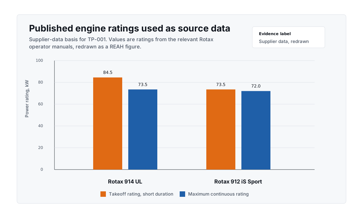
Figure 2. Published rating values used as TP-001 source data, redrawn by REAH rather than reproduced from supplier charts. Takeoff ratings are short-duration; continuous ratings are the relevant starting point for long-endurance mission analysis.
Hot-Day Derating
Both engines are affected by high ambient temperature. Turbocharging helps with altitude normalization, but it does not make hot-day operation disappear. At 45 °C, intake-air density, charge temperature, oil temperature, coolant temperature and installation heat soak all move in the wrong direction.
In the paper, the published Rotax temperature-correction method is applied before drawing mission conclusions. The result is intentionally framed as a corrected system comparison, not a simple reading of headline ratings.
Figure 3
Hot-day derating
Electrical Generation Load
Modern UAVs often carry continuous electrical loads for payloads, mission computers, communications, avionics and thermal-control hardware. A 5 kW electrical load is not free from the propulsion system.
Using the paper assumption:
Electrical load = 5.00 kW
Generator efficiency = 90%
Mechanical demand = 5.00 / 0.90 = 5.56 kW
That mechanical demand must come from the engine before the remaining shaft power can be treated as propulsion power. For a long-endurance mission, this subtraction may matter more than a short-duration takeoff rating.
In the representative calculation prepared for TP-001, the continuous propulsion advantage of the 914 becomes small once hot-day correction and continuous electrical generation are considered together. The exact value should be published only with the final data table and citations.
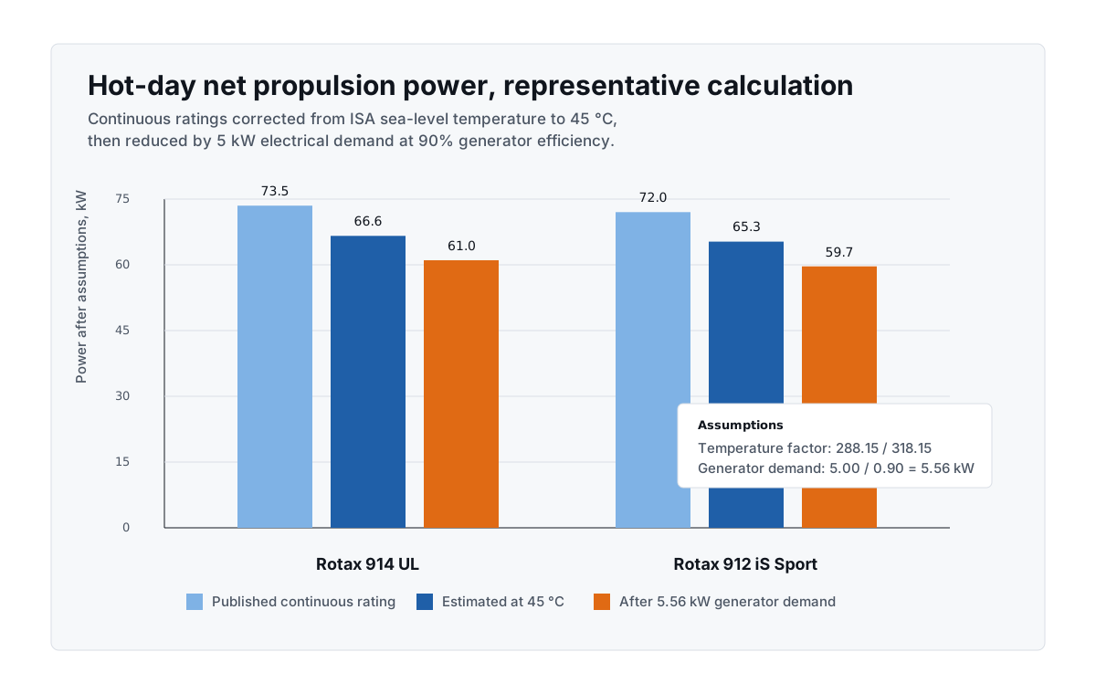
Figure 4. Representative calculation using published continuous ratings, a simple temperature correction from ISA sea-level temperature to 45 °C, and a 5 kW electrical load at 90% generator efficiency. This is a mission-analysis illustration, not a measured flight-test result.
Mission-Power Timeline
The 914's 115 hp figure is a short-duration rating under defined conditions. It is valuable when the aircraft can use it and when the mission demands it. A launcher-assisted low-altitude UAV may spend only a small part of its useful mission near that operating point.
The paper therefore separates:
- launch requirement
- climb requirement
- continuous loiter requirement
- electrical power requirement
- thermal-management requirement
This prevents the aircraft from being optimized around the most visible number while under-weighting the condition that dominates endurance, heat rejection and fuel consumption.
Figure 5
Mission-power timeline
Pusher Installation Effects
Pusher UAVs can be thermally difficult because the propulsion system often sits in disturbed flow, near exhaust heat, with restricted inlet and outlet options. The aircraft may also have limited ram pressure during launch, climb and loiter.
The analysis should include:
- cooling-air recirculation near the engine bay
- oil-cooler airflow and pressure recovery
- exhaust heat shielding and local component temperatures
- radiator inlet uniformity
- outlet pressure and cooling drag
- propeller-slipstream effects
Original CFD figures are appropriate when available, provided they are labelled as simulated, preliminary or validated as applicable. The paper should not imply a completed test campaign unless the underlying measurements exist.
Turbocharging Without an Intercooler
Turbocharging compresses the intake charge and can preserve manifold pressure at altitude. Compression also raises charge-air temperature. Without intercooling, the downstream thermal consequences become part of the installation problem.
For hot-climate pusher UAVs, the paper treats this carefully:
- charge-air temperature rise is a physics issue
- engine-bay heat soak is an installation issue
- cooling-air recirculation is an aircraft-layout issue
- measured engine performance must not be inferred beyond the available data
This distinction matters. The paper should explain the thermal burden without overstating conclusions that require instrumented testing.
Life-Cycle Cost
TP-001 treats life-cycle cost as an engineering variable, not an accounting appendix.
The comparison should include:
- acquisition cost of the engine and associated installation hardware
- engineering cost for cooling, exhaust, shielding, ducting and validation
- additional CFD and ground-test iterations required by tighter thermal margins
- cooling drag and any endurance penalty caused by larger cooling installations
- inspection burden and maintenance access
- opportunity cost of mass, volume and engineering time
The opportunity-cost question is often the most useful one: could the mass, volume, cost and validation effort required by the more complex installation be better spent on fuel, payload, sensors, batteries, computing or cooling margin?
Mission Suitability Matrix
The paper's conclusion should not be universal. Different missions weight the trade differently.
| Mission context | Likely implication |
|---|---|
| High-altitude ISR | Turbocharging may be mission critical |
| Mountain operations | Altitude normalization can be valuable |
| Hot low-altitude ISR | Thermal margin and continuous power dominate |
| Maritime patrol at modest altitude | Endurance, fuel burn and maintainability may dominate |
| Catapult-launched loiter mission | Short-duration takeoff horsepower may be less decisive |
| Heavy sustained climb | Continuous power and cooling capacity must be checked carefully |
Figure 6
Mission-suitability matrix
This matrix is a decision aid, not a replacement for aircraft-specific analysis.
Preliminary Conclusion
The Rotax 914 remains a strong engine when altitude normalization is central to the mission. For aircraft that genuinely need its turbocharged performance envelope, the added integration work may be justified.
For launcher-assisted UAVs operating mostly below approximately 8,000 ft in hot climates, the picture is different. Once continuous power, 45 °C operation, a 5 kW electrical load, pusher-installation cooling and life-cycle cost are included, the 914's practical propulsion advantage can become much smaller than the headline specification suggests.
The engine choice should therefore be based on complete mission analysis:
- What power is needed after launch, during the actual mission?
- What net propulsion power remains after electrical generation?
- What happens at the design hot-day condition?
- How much cooling drag and installation mass are required?
- What validation burden does the aircraft inherit?
- What mission value is purchased by the added complexity?
The answer may still be the 914. The point is that the answer should come from the mission.
References
- BRP-Rotax, Operator's Manual for Rotax Engine Type 914 Series — supplier data for operating limits, ratings and correction methods.
- BRP-Rotax, Operator's Manual for Rotax Engine Type 912 i Series — supplier data for operating limits, ratings and correction methods.
- BRP-Rotax, Installation Manual for Rotax Engine Type 914 Series — installation guidance relevant to cooling, exhaust and turbocharger integration.
- BRP-Rotax, Installation Manual for Rotax Engine Type 912 i Series — installation guidance relevant to cooling, electrical architecture and engine management.
- F. W. Meredith, Note on the Cooling of Aircraft Engines with Special Reference to Ethylene Glycol Radiators Enclosed in Ducts, ARC R&M 1683, 1936.
- D. Kuchemann and J. Weber, Aerodynamics of Propulsion, McGraw-Hill, 1953.